Understanding the N-Channel FET Symbol: A Simple Guide to Unlocking its Power
Understanding the N-Channel FET Symbol: A Simple Guide to Unlocking its Power
In the world of electronics and engineering, Field-Effect Transistors (FETs) are a crucial component in modern devices, from smartphones to microcontrollers. Among the various types of FETs, the N-Channel FET is a popular choice due to its high switching speed and low power consumption. However, understanding the N-Channel FET symbol can be a daunting task for newcomers to the field. This article aims to provide a comprehensive guide to the N-Channel FET symbol, explaining its significance, functionality, and how it is used in real-world applications.
The N-Channel FET symbol is a three-terminal device consisting of a gate, drain, and source. It is called an N-Channel FET because it has a negatively charged channel that controls the flow of current between the drain and source terminals. The gate terminal, on the other hand, acts as a control gate, regulating the flow of current by applying a voltage. When a voltage is applied to the gate, it creates an electric field that controls the flow of electrons through the channel, thereby controlling the current flow between the drain and source. As Robert Fontana, a renowned electronics engineer, puts it, "The N-Channel FET is a highly versatile device that can be used in a wide range of applications, from digital logic circuits to power amplifiers."
Key Components of the N-Channel FET Symbol
The N-Channel FET symbol consists of six main components:
* Drain (D): This is the terminal where the voltage output is collected.
* Source (S): This is the terminal where the input voltage is applied.
* Gate (G): This is the control terminal that regulates the flow of current between the drain and source.
* Channel: This is the semiconductor material that controls the flow of current between the drain and source.
* Source-Drain Resistance (Rs): This is the resistance between the source and drain terminals.
* Channel Resistance (Rch): This is the resistance within the channel itself.
The Drain and Source terminals are used to connect the N-Channel FET to other components in a circuit, while the Gate terminal is used to control the flow of current.
How the N-Channel FET Works
The N-Channel FET works by using the voltage applied to the gate terminal to control the flow of current between the drain and source terminals.
When a positive voltage is applied to the gate, it creates an electric field that repels the electrons in the channel, creating a region of low electron concentration near the gate. This results in a low current flow between the drain and source. On the other hand, when a negative voltage is applied to the gate, it attracts the electrons in the channel, creating a region of high electron concentration near the gate. This results in a high current flow between the drain and source.
The N-Channel FET has two main operating modes:
* Enhancement Mode: In this mode, the N-Channel FET conducts when a sufficient voltage is applied to the gate.
* Depletion Mode: In this mode, the N-Channel FET conduct when the gate is grounded or a negative voltage is applied.
Applications of N-Channel FETs
N-Channel FETs are widely used in a variety of applications due to their high switching speed, low power consumption, and versatility.
* Digital Logic Circuits: N-Channel FETs are used as logic gates, such as AND, OR, and XOR gates, to perform logical operations.
* Power Amplifiers: N-Channel FETs are used in power amplifiers to amplify low-voltage signals.
* DC-DC Converters: N-Channel FETs are used in DC-DC converters to convert DC voltage inputs to other DC voltage outputs.
* Motor Control Circuits: N-Channel FETs are used in motor control circuits to control the speed and direction of DC motors.
“N-Channel FETs are a fundamental building block of digital electronics, providing a high level of current gain, fast switching speed, and low noise.” - Asa Mearl, Electronics EngineerCommon N-Channel FET Types
Some common N-Channel FET types include:
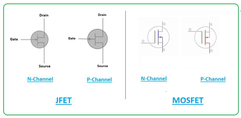
* N-Channel JFETs: These FETs use a junction barrier to control the flow of current.
* N-Channel MOSFETs: These FETs use a thin oxide layer to control the flow of current.
* N-Channel IGBTs: These FETs use a combination of a BJT and a MOSFET to control the flow of current.
When selecting an N-Channel FET for a particular application, it is essential to consider factors such as power dissipation, current gain, and switching speed. The specific type of N-Channel FET chosen will depend on the specific requirements of the application.
Conclusion
In conclusion, the N-Channel FET symbol is a crucial component in modern electronics, offering a high level of versatility and reliability. Understanding the N-Channel FET symbol and its key components is essential for engineers and electronics enthusiasts to unlock its full potential. With this comprehensive guide, readers should now have a clear understanding of the N-Channel FET symbol and its applications.
“A simple guide to the N-Channel FET symbol can help engineers and electronics enthusiasts master this fundamental device and unleash their creativity in innovative circuit design.” - Harvey Lauder, Electronics Engineer


Related Post

The Ultimate Road Trip: A Comprehensive Guide to Houston to Lubbock Drive

Marjorie Taylor Greene's Towering Presence: Unpacking the Georgia Congresswoman's Height

Get Ready to Rent: Zillow Houses For Rent In North Carolina Coming Soon!

The Whirlwind Romances of Benny Blanco: A Decade of Love and Music